 |
 |
 |
 |
| HOME |
| ABOUT US |
| PARTICIPATE |
| COLLECTIONS |
| DC EQUIPMENT MUSEUM |
| SHIP&SUBMARINE MUSEUM |
| WW II DAMAMGE REPORTS |
| SHIPBOARD CASUALTIES |
| DAMAGE CONTROL MUSEUM |
| DC EQUIPMENT Museum |
| Firefighting Systems |
| Firemain |
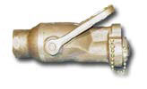
No matter how new and the excellent condition firefighting equipment was in, it was of very little use if the fire main was fouled with barnacles and marine growth. This growth accumulated on the inside of the piping and valves, reducing the volume of water flow to a trickle and preventing proper closing of the valves and isolation of the system in the event of damage. It was imperative that all ships have a viable fire main maintenance program, including flushing of the fire main with fresh water at specified intervals. Most fire main piping was galvanized. Beginning in 1943, some ships had a plastic coating applied to the inside of the piping to help reduce fouling. Application was done in sections. Hopefully after a few up-keep periods the entire fire main was coated. A few of the new cruisers started to have copper nickel fire main piping installed by 1943 and early 1944. Also, by 1943, all shipboard fire plugs began to have self-cleaning strainers installed. The purpose of these was to reduce the marine growth at the nozzle by straining the water. This was extremely important for sprinkler and applicator head nozzle orifices, as it prevented clogging and allowed water to flow as required for firefighting. No information was or is of greater importance to the damage control organization than a complete knowlege of the firemain system. War exsperience has demonstrated that a ship can be lost by fire through failure to sectionalize the firemain system into a reasonable number of seperate and independent systems. Ordinarily, the fire main supplies water pressure for several other cruising and battle systems. Among them are the flushing system, magazine sprinkling system, fuel-oil tank ballast system, eductors, gasoline drainage system, salt water displacement systems, and cooling systems for various machinery units such as oil coolers. The capacity of a fire-fighting system is designed to simultaneously fight a number of fires, yet reserve sufficient water to sprinkle spaces containing hazardous material and to supply certain vital services. Careful consideration of valve settings is essential in order not to "starve risers" supplying fire hoses when emergencies require diversion of some of the system's capacity for sprinkling magazines or pumping flooded spaces. The possibility of such simultaneous demands must be foreseen, and preparations made to meet the situation. The firemain is made up of pumps, piping, valves and controls. The firemain system is design to have suffcient capacity and flexibility to permit diversion of some pumps for several other piping systems -magazine-sprinklet· systems, flushing fuel-oil tank ballast systems, gaso-line systems, drainage systems ( ednctors), and cooling water service in machinery compartments-without dangerous de-crease in fire main pressure or delivery for fire fighting. Any pump installed for use as a fire pump must be designed to deliver an adequate volume of water at a pressure sufficient to operate fog nozzles efficiently at the upper deck levels. On the largest ships fire pumps are designed to operate at 150 pounds per square inch pressure; on destroyers the corresponding figure is 100 pounds per square inch pressure. Different types of pumps are installed in fire mains. They may be classified as follows: 1. Steam driven reciprocating fire and bilge pumps. 2. Centrifugal pumps, driven by: a. Steam turbines. b. Electric motors. c. A combination of turbines and electric motors. d. Diesel engines. The steam-driven reciprocating pump were very reliable, and usually is located in a boiler room or machinery space in close proximity to a source of steam. Its capacity is relatively small, however, running from 100 to 400 gallons per minute. This is a standard fire pump for small ships up to the size of the later destroyers. As the size of the ship increases this type of pump is supplemented, and, in the latest large ships its customary fire-main services are entirely provided This was a standard fire pump for small ships up to the size of the later destroyers. As the size of the ship increases this type of pump is supplemented, and, in the latest large ships its customary fire-main services are entirely provided The piping of the fire main system is either a straight line (on small ships) or a loop system (on larger ships). Risers go from the fire main to fire plugs on the upper deck levels. The fire main system is so designed that any damaged section of piping can be isolated. For a complete, knowledge, of the system, it is necessary to trace the fire main throughout the ship, noting the location of risers, cross-connecting and shut-off valves, and fire pumps. In addition to isolating with valves, it will be necessary to continue supplying water through the undamaged sections. Here a knowledge of the fire plug location and technique for rigging jumpers will aid in providing firemain pressure for fire fighting and operation of equipment. 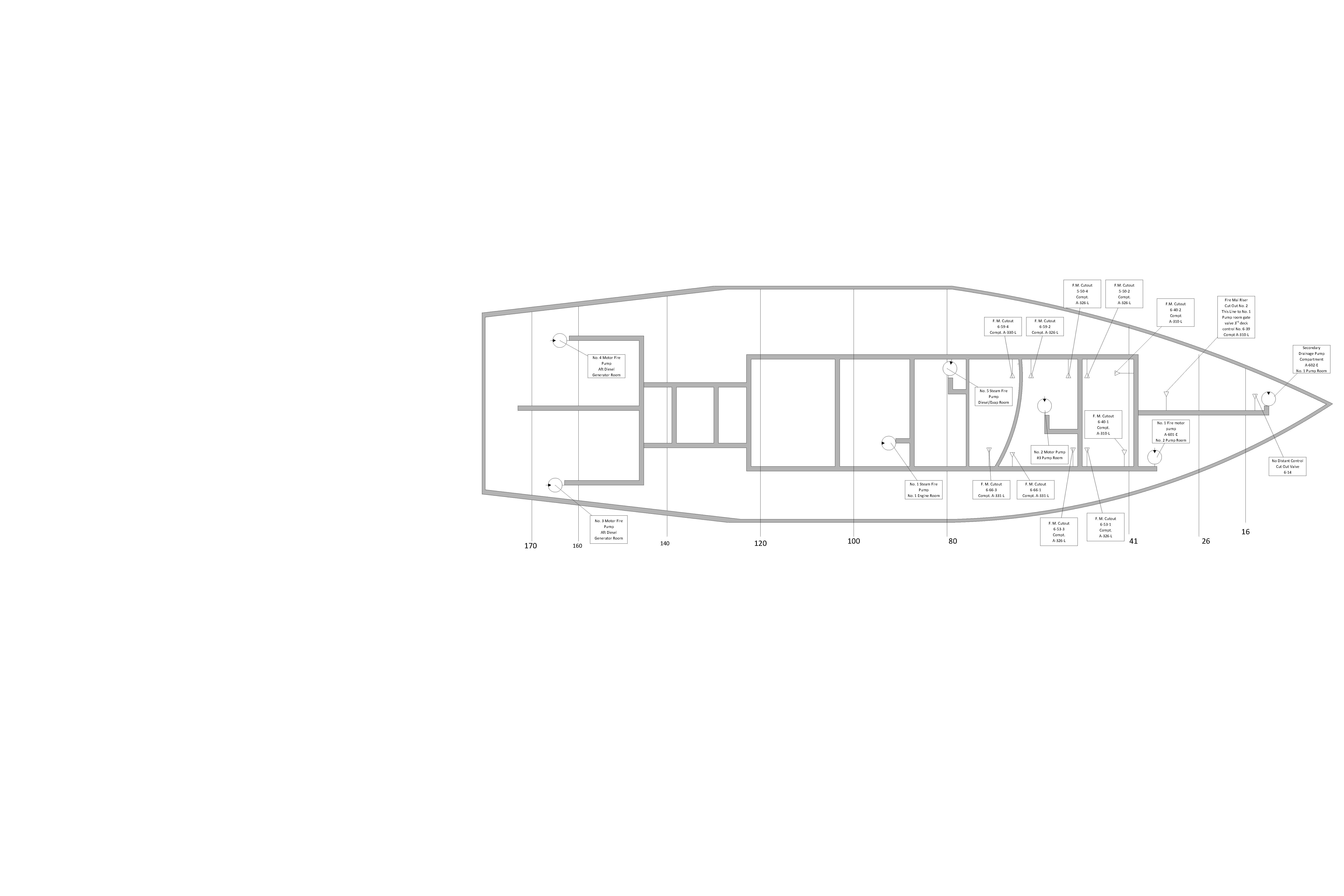 Battle ship firemain system diagram In practically all ships, the fire-main piping was arranged in compartments that sections of piping and valves may be dismantled by the ship's force for repairs, using regular shipboard tools. If a section of piping is ruptured, cut-out valves on either side of the break may be closed and the ruptured section removed by unbolting the appropriate flanges. Temporary service may be restored by connecting a length of fire hose between the open flanges. Damage control hose-flange adapters are provided in repair stations so that such temporary connections or, jumpers may be rigged. These hose-flange adapters can be bolted (or clamped with C-clamps) into place easily and quickly. The damaged section of piping should, of course, be repaired and put back into place as soon as possible All piping systems were color coded firemain was normally indicated by 2 green stripes 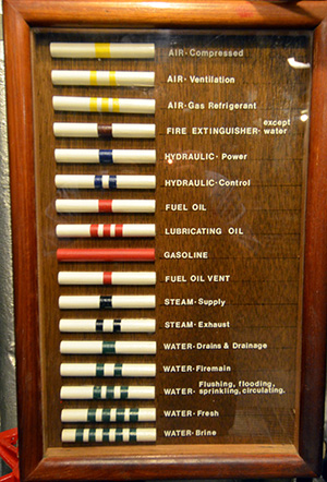 Piping System color coding chart 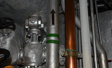 Firemain piping from an anf engineering space supplying the rest of the ship For more information, see the Index. |